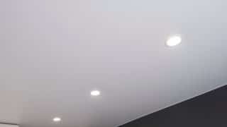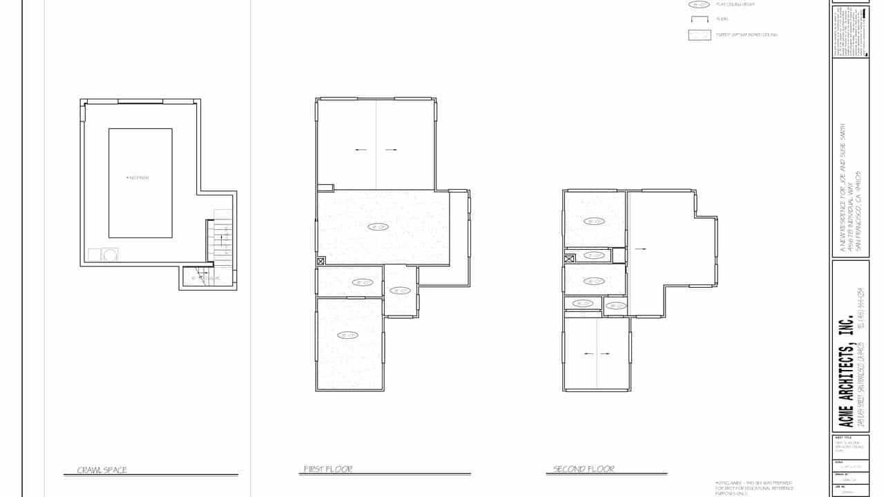
A reflected ceiling plan (RCP) is a print that shows you the dimensions, materials, and other key information about the ceiling of each of the rooms represented on your blueprint. It takes its name from the idea that you are looking down at the ceiling as though there were a mirror on the floor reflecting the ceiling’s plan back to you.
Architects and builders draw reflected ceiling plans this way so that the orientation of the floor plan and the orientation of the ceiling plan are the same—and therefore easier to read. In other words, you are looking down at a view of both the ceiling and the floor.
In his Introduction to Reading Blueprints course, builder and craftsman Jordan Smith explains:
“Sometimes we’ll do a reflected ceiling plan on the floor plan, which means that whatever’s happening up on the ceiling is reflected down on the floor and then drawn for our benefit as builders.”
Think of it as an engineering document that is separate from the architectural drawing.
What is the purpose of an RCP?
An RCP includes information that nearly everyone involved in the building process needs, from interior designers and architects to electricians and plumbers. This part of the plan includes vital information about light fixtures and lighting plans, HVAC mounts, plus sprinklers, smoke detectors, any equipment that requires special venting, and any other mechanical or electrical object on the ceiling.
The main function of an RCP in a set of blueprints is to allow the interior designer or architect to see how lighting functions in the room. But first, a builder or engineer will need to establish the ceiling-to-floor balance and add those dimensions in the layout. Those dimensions will include the height of the ceiling as well as the slope or the slant across the project, or features like vaults or embellishments, and the level of insulation.
Because it supports various components, the ceiling is one of the most functional aspects of a space. You’ll see the materials described in the plan, such as wallboards made of gypsum, which are installed on the ceiling. A suspended system creates a space between the ceiling and the flooring above it (or the roof) to conceal wiring and circuits. A ceiling might also have an exposed system—such as wooden beams—which support the panels that hide the various service components.
When an architect or interior designer looks at the RCP, they can see the structural layout of the space and insert the lighting requirements needed for each room. They’ll see the electrical plans to lay out the requirements, so the dimmers, electrical and telecom connections, and panel boards are shown.
How to Read Blueprints
A reflected ceiling plan (RCP) is a print that shows you the dimensions, materials, and other key information about the ceiling of each of the rooms represented on your blueprint. It takes its name from the idea that you are looking down at the ceiling as though there were a mirror on the floor reflecting the ceiling’s plan back to you.
Architects and builders draw reflected ceiling plans this way so that the orientation of the floor plan and the orientation of the ceiling plan are the same—and therefore easier to read. In other words, you are looking down at a view of both the ceiling and the floor.
In his Introduction to Reading Blueprints course, builder and craftsman Jordan Smith explains:
“Sometimes we’ll do a reflected ceiling plan on the floor plan, which means that whatever’s happening up on the ceiling is reflected down on the floor and then drawn for our benefit as builders.”
Think of it as an engineering document that is separate from the architectural drawing.
What is the purpose of an RCP?
An RCP includes information that nearly everyone involved in the building process needs, from interior designers and architects to electricians and plumbers. This part of the plan includes vital information about light fixtures and lighting plans, HVAC mounts, plus sprinklers, smoke detectors, any equipment that requires special venting, and any other mechanical or electrical object on the ceiling.
The main function of an RCP in a set of blueprints is to allow the interior designer or architect to see how lighting functions in the room. But first, a builder or engineer will need to establish the ceiling-to-floor balance and add those dimensions in the layout. Those dimensions will include the height of the ceiling as well as the slope or the slant across the project, or features like vaults or embellishments, and the level of insulation.
Because it supports various components, the ceiling is one of the most functional aspects of a space. You’ll see the materials described in the plan, such as wallboards made of gypsum, which are installed on the ceiling. A suspended system creates a space between the ceiling and the flooring above it (or the roof) to conceal wiring and circuits. A ceiling might also have an exposed system—such as wooden beams—which support the panels that hide the various service components.
When an architect or interior designer looks at the RCP, they can see the structural layout of the space and insert the lighting requirements needed for each room. They’ll see the electrical plans to lay out the requirements, so the dimmers, electrical and telecom connections, and panel boards are shown.
RCPs are only one component of a property’s blueprints. Learn everything you need to know about reading blueprints in MT Copeland’s online class, taught by professional builder and craftsman Jordan Smith.
What is the difference between an RCP and a floor plan?
Although the orientation of the floor plan and reflected ceiling plan are the same, they serve very different functions. The simplest way to think of this is that the floor plan shows the placement of various features on the floor, such as doors and windows, stairwells, and even furniture.
Floor plans and RCPs include so much information that if you were to look at all of these things at once, the plan would be crowded. The RCP removes the visual congestion of lighting plans, mechanical, and other engineering features and separates them on their own page for easy reference.


What symbols are used on RCPs?
Since the RCP is an engineering drawing separate from the architectural drawing, it includes symbols specific to light fixtures, special ceiling features, ceiling supply registers, and other elements specific to the RCP.
For instance, on this plan, the engineer has included supply registers with the arrows going out and return registers with arrows coming in. You’ll see these special symbols on the RCP plan, and sometimes on a floor plan that includes other elements, so that the architect can understand how they fit into the context of the entire room.

MT Copeland offers video-based online classes that give you a foundation in construction fundamentals with real-world applications. Classes include professionally produced videos taught by practicing craftspeople, and supplementary downloads like quizzes, blueprints, and other materials to help you master the skills.

Featured Instructor
Jordan Smith
Jordan Smith is the CEO and Founder of Smith House Company, a design+build firm based in Austin, Texas. He learned to build and weld while working on the farm with his grandad, and after earning a degree in Welding and Materials Engineering, he spent the next 10 years working in the heavy construction building everything from robots to ships to offshore oil rigs before transitioning to residential construction. After spending a couple of years working with industry leading builders in Austin, Jordan and his wife Veronica struck out on their own to form Smith House Co. Smith House Co. strives to build more beautiful, functional and resilient spaces which are self sustaining and harmonize with their natural surroundings.
Explore Classes
