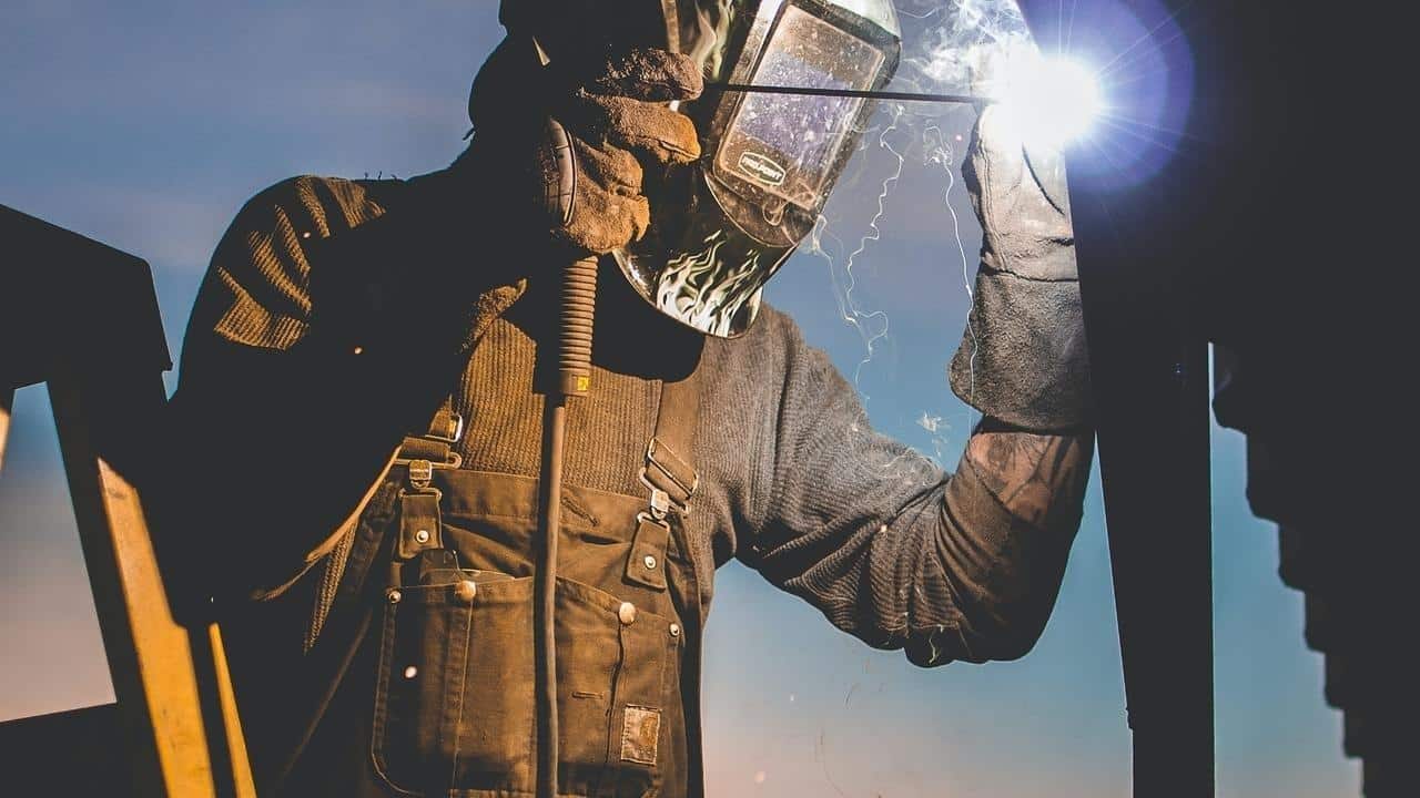
Alongside subcontractors who handle plumbing, HVAC (that is heating, ventilation, and air conditioning), and electricians, welders are often key members of the team involved in the construction of a building.
Welders will work closely with plumbing engineers to assure that connections between pipes, both supply and wastewater, are solid and secure. A welder’s services may also be needed for structural elements as with, for example, a steel frame building where columns, beams, and trusses may be welded to other supports. Finally, you may find yourself calling a welder for the installation of some non-structural or architectural steel elements such as stair rails, awnings, vent hoods or shelving.
Though welding symbols are usually reserved for shop drawings from fabricators, builders should know how to recognize them on structural drawings within a set of blueprints, as builders are responsible for making sure the various aspects of a construction project are coming together as intended.
“Good builders need to know what a welding symbol looks like,” explains professional builder and craftsman Jordan Smith. “That way when you encounter it, you’re able to say, ‘Hey, this is beyond what I’m doing with framing. I need to coordinate with the fabricator to make sure that all of these connections happen appropriately.’”
For example, an architect includes a staircase with a metal handrail in the design of the house. That is then sent to a fabricator who will build the metal handrail, and who knows where and how the different elements of it should be welded together. The fabricator’s drawings are sent back to the architect for review, but he or she isn’t looking at the types of welds or the engineering of it, just whether it looks like how the architect envisioned it. The contractor and the welder will then work from the fabricator’s drawings for the details of installing the handrail.
Recognizing symbols is a first step towards reading a property’s blueprints. Learn everything you need to know about reading blueprints in MT Copeland’s online class, taught by professional builder and craftsman Jordan Smith.
6 Common welding symbols
1. Arrowhead and reference line
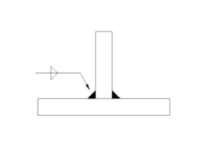
This allows you to quickly identify that you are looking at a weld symbol. The arrow points at the joint where the weld will be placed, while information about the orientation and type of weld will be included along the arrow side, or reference line. (Image via openoregon.pressbooks.pub)
2. Type of weld
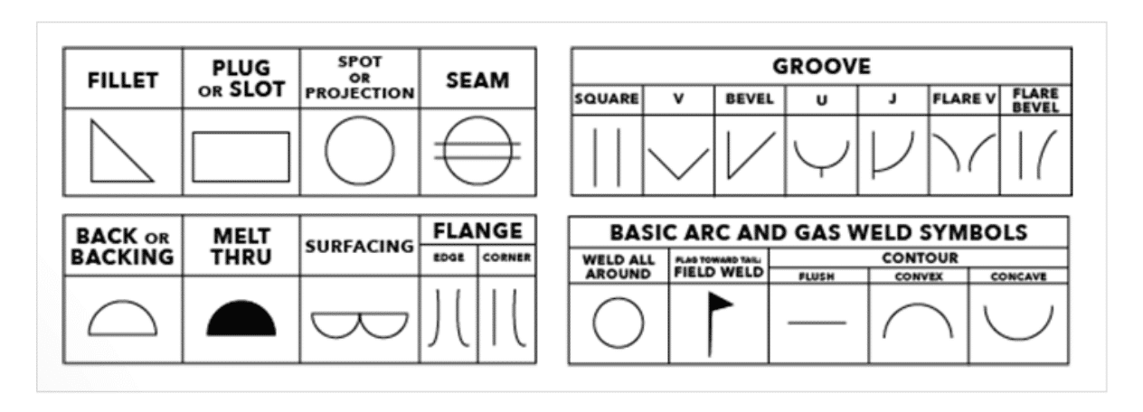
Along the sides of the reference line, a symbol representing either the joint design or the completed weld will indicate the type of weld, with common groove weld symbols including vee butt joints, bevel joints, and fillet welds. Spot welds are indicated by circles and seam welds by a circle crossed by two parallel lines. (Image via weldingsuppliesfromioc.com)
3. Placement or orientation of the weld
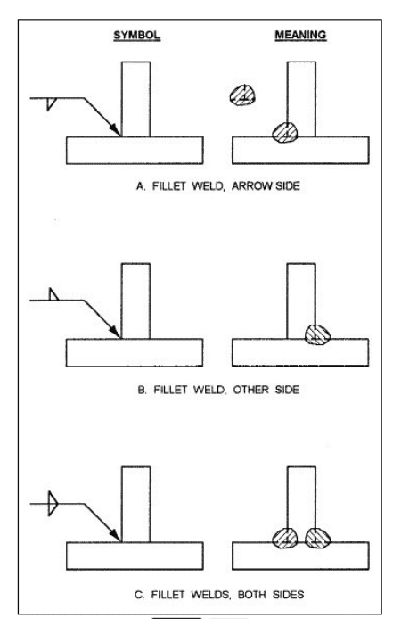
If the symbol for the type of weld appears below the reference line, then the weld should be on the same side of the joint as the arrow. If it is above the reference line, then it goes on the opposite side of the joint. If the symbol is repeated both above and below the reference line, then both sides of the joint should be welded. (Image via wcwelding.com)
Alongside subcontractors who handle plumbing, HVAC (that is heating, ventilation, and air conditioning), and electricians, welders are often key members of the team involved in the construction of a building.
Welders will work closely with plumbing engineers to assure that connections between pipes, both supply and wastewater, are solid and secure. A welder’s services may also be needed for structural elements as with, for example, a steel frame building where columns, beams, and trusses may be welded to other supports. Finally, you may find yourself calling a welder for the installation of some non-structural or architectural steel elements such as stair rails, awnings, vent hoods or shelving.
Though welding symbols are usually reserved for shop drawings from fabricators, builders should know how to recognize them on structural drawings within a set of blueprints, as builders are responsible for making sure the various aspects of a construction project are coming together as intended.
“Good builders need to know what a welding symbol looks like,” explains professional builder and craftsman Jordan Smith. “That way when you encounter it, you’re able to say, ‘Hey, this is beyond what I’m doing with framing. I need to coordinate with the fabricator to make sure that all of these connections happen appropriately.’”
For example, an architect includes a staircase with a metal handrail in the design of the house. That is then sent to a fabricator who will build the metal handrail, and who knows where and how the different elements of it should be welded together. The fabricator’s drawings are sent back to the architect for review, but he or she isn’t looking at the types of welds or the engineering of it, just whether it looks like how the architect envisioned it. The contractor and the welder will then work from the fabricator’s drawings for the details of installing the handrail.
Recognizing symbols is a first step towards reading a property’s blueprints. Learn everything you need to know about reading blueprints in MT Copeland’s online class, taught by professional builder and craftsman Jordan Smith.
6 Common welding symbols

1. Arrowhead and reference line
This allows you to quickly identify that you are looking at a weld symbol. The arrow points at the joint where the weld will be placed, while information about the orientation and type of weld will be included along the arrow side, or reference line. (Image via openoregon.pressbooks.pub)

2. Type of weld
Along the sides of the reference line, a symbol representing either the joint design or the completed weld will indicate the type of weld, with common groove weld symbols including vee butt joints, bevel joints, and fillet welds. Spot welds are indicated by circles and seam welds by a circle crossed by two parallel lines. (Image via weldingsuppliesfromioc.com)

3. Placement or orientation of the weld
If the symbol for the type of weld appears below the reference line, then the weld should be on the same side of the joint as the arrow. If it is above the reference line, then it goes on the opposite side of the joint. If the symbol is repeated both above and below the reference line, then both sides of the joint should be welded. (Image via wcwelding.com)

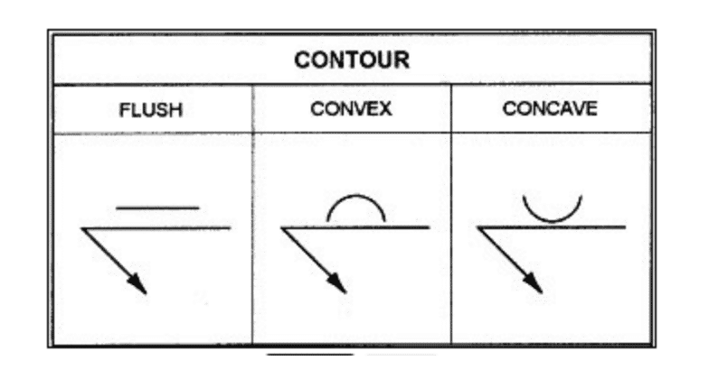
4. Weld contour
Whether a weld should be flush, concave, or convex is indicated by a line along the symbol representing the type of weld. A flush weld is indicated by a straight line, concave and convex welds are indicated by curved lines. (Image via wcwelding.com)
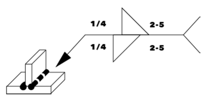
5. Size of weld
Numbers to both sides of the basic weld symbol indicate its size. The number to the left of the weld symbol indicates its width and the one to its right indicates its length. Sometimes there will be two numbers to the right of the symbol, separated by a dash. If that is the case then there are multiple welds, as is the case with intermittent fillet welds, and the second number indicates the distance between the centers of each individual weld. With a fillet weld, if the fillet weld symbol appears both above and below the reference line with the same number to its left in each place, the welder should create an equal legged weld. (Image via weldingsuppliesfromioc.com)

6. Supplementary symbols
One of the most important pieces of supplemental information from the perspective of the contractor is a small flag placed along the reference line. This indicates that the weld is a field weld (that is, one that should be made on site).
Other details about the type of weld or how it is to be made can be added in the tail of the arrow. (If there is no extra information that has to be provided to the welder, the tail will typically be omitted.)
Often this supplemental information comes in the form of an abbreviation which, in the United States, is based on reference codes from the American Welding Society and indicates a particular welding process. For example, FCAW refers to flux cored arc welding while SMAW represents shielded metal arc welding (both are commonly used in construction).
While you are less likely to come across them in the United States, you may also find numbers in the tail of the weld. If you do, these are ISO codes from the International Organization for Standardization (136 is equivalent to FCAW; 111 to SMAW). (Image via wcwelding.com)
MT Copeland offers video-based online classes that give you a foundation in construction fundamentals with real-world applications. Classes include professionally produced videos taught by practicing craftspeople, and supplementary downloads like quizzes, blueprints, and other materials to help you master the skills.


