Eight types of construction drawings used in commercial construction
Apr 09, 2021

Blueprints, plans, drawings—in construction, these three terms all refer to the same thing. These are technical drawings created by architects, engineers, and designers to represent the vision for a construction project, and act as a roadmap for making it a reality.
Professional carpenter Elly Hart explains in her class on reading commercial blueprints, “Construction blueprints aren’t just drawings—they’re a contract that represents what’s going to be built, and it’s a critical form of communication that gets everybody involved on the same page. It’s the one shared goal for all the different trades on site.”
8 Types of construction drawings
There are 8 main types of construction drawings included in a set of commercial blueprints. The same types of drawings also appear in residential construction, but their scope and specific contents will differ. Elly Hart explains:
“On commercial projects, blueprints are typically separated by discipline. The architectural drawings are separate to the structural drawings, which are separate to the mechanical drawings, and so on. A complete set of IFCs will often contain hundreds and hundreds of sheets. There will often be multiple floors, multiple sets of stairs, multiple components that look the same but have important differences depending on their purpose and location, and they all need to be uniquely identifiable on the plans.”
Below is a detailed description of each type of construction drawing you’ll encounter in a set of commercial blueprints.
Site Plans
Site plans are a type of architectural drawing that functions as a map of a building site, giving you the details you need to know about how the structure will be oriented on the lot. An architect will create a diagram that shows the plot of land and its property lines, along with its landscape features, setbacks, driveways, utility poles and power lines, fencing, and on-site structures.
Floor Plans
A floor plan is a bird’s eye view of a building, giving you a detailed picture of the layout of each floor. It includes features such as walls, doors, windows, means of egress, and sometimes even furniture.
Reflected Ceiling Plans (RCP)
The RCP is a print that shows you the dimensions, materials, and other key information about the ceiling of each of the rooms represented on your blueprint. It takes its name from the idea that you are looking down at the ceiling as though there were a mirror on the floor reflecting the ceiling’s plan back to you.

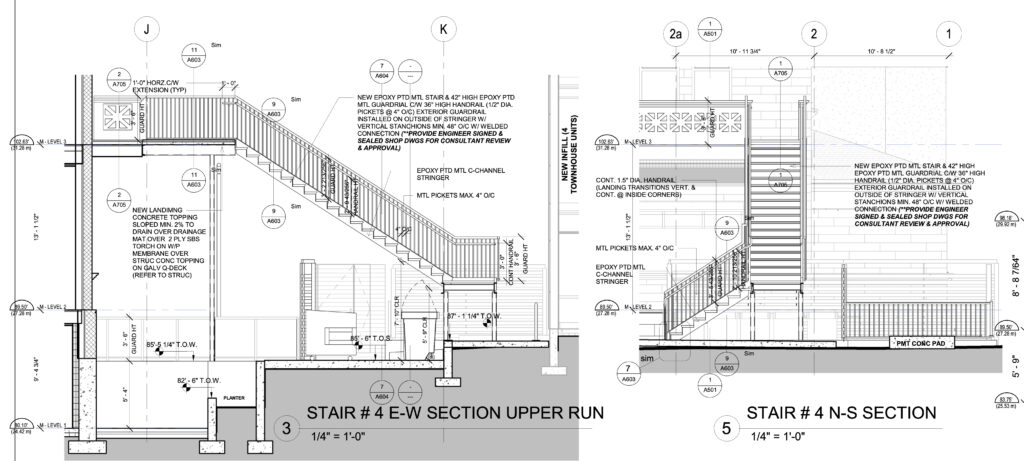
Sections
While a floorplan gives a horizontal view of a floor in a building, sections give a vertical view. A sectional view shows the floor elevations, ceiling heights, and construction details such as fire separations. While a floor plan allows for a view of how the walls stand in relation to each other, a section shows where the wall meets the floor, and the distance that separates one floor from another. Sections also provide a better understanding of how a building’s spaces will accommodate its future occupants and whether, for example, the ceiling will feel like it looms or soars overhead.

Blueprints, plans, drawings—in construction, these three terms all refer to the same thing. These are technical drawings created by architects, engineers, and designers to represent the vision for a construction project, and act as a roadmap for making it a reality.
Professional carpenter Elly Hart explains in her class on reading commercial blueprints, “Construction blueprints aren’t just drawings—they’re a contract that represents what’s going to be built, and it’s a critical form of communication that gets everybody involved on the same page. It’s the one shared goal for all the different trades on site.”
8 Types of construction drawings
There are 8 main types of construction drawings included in a set of commercial blueprints. The same types of drawings also appear in residential construction, but their scope and specific contents will differ. Elly Hart explains:
“On commercial projects, blueprints are typically separated by discipline. The architectural drawings are separate to the structural drawings, which are separate to the mechanical drawings, and so on. A complete set of IFCs will often contain hundreds and hundreds of sheets. There will often be multiple floors, multiple sets of stairs, multiple components that look the same but have important differences depending on their purpose and location, and they all need to be uniquely identifiable on the plans.”
Below is a detailed description of each type of construction drawing you’ll encounter in a set of commercial blueprints.
Site Plans
Site plans are a type of architectural drawing that functions as a map of a building site, giving you the details you need to know about how the structure will be oriented on the lot. An architect will create a diagram that shows the plot of land and its property lines, along with its landscape features, setbacks, driveways, utility poles and power lines, fencing, and on-site structures.
Floor Plans
A floor plan is a bird’s eye view of a building, giving you a detailed picture of the layout of each floor. It includes features such as walls, doors, windows, means of egress, and sometimes even furniture.
Reflected Ceiling Plans (RCP)
The RCP is a print that shows you the dimensions, materials, and other key information about the ceiling of each of the rooms represented on your blueprint. It takes its name from the idea that you are looking down at the ceiling as though there were a mirror on the floor reflecting the ceiling’s plan back to you.
Sections
While a floorplan gives a horizontal view of a floor in a building, sections give a vertical view. A sectional view shows the floor elevations, ceiling heights, and construction details such as fire separations. While a floor plan allows for a view of how the walls stand in relation to each other, a section shows where the wall meets the floor, and the distance that separates one floor from another. Sections also provide a better understanding of how a building’s spaces will accommodate its future occupants and whether, for example, the ceiling will feel like it looms or soars overhead.

Structural Drawings
Engineers create structural drawings to show how the building will be framed, and how it will be given its structure. You’ll see a structural drawing for each floor of the building, including floors below grade such as parkades and storage.
Mechanical, Electrical, and Plumbing (MEP) Drawings
MEP drawings show the central nervous system of a building. Describing these functions, from ensuring its air quality to planning its electronic and communications systems, to laying out complex piping routes, is the responsibility of MEP engineers.
- The mechanical plans show the heating, ventilation, and air conditioning (or HVAC) systems of a building.
- The electrical plans show how the electrical system will provide the power supply for lights and appliances, as well as access control and fire alarm systems. Electrical engineers design the routes for wiring so they can be safely and continuously operated.
- Plumbing plans reflect the complex piping and sewage routes for the building, as well as heated water and rainwater collection and storage.
Schedules
Schedules are drawings showing supplementary information, typically presented in tables, that go beyond the details that can be found on the floor plans. Window and door schedules provide the additional information that a contractor will need in order to install these items: the different types of windows and doors to be used in a building, their locations, and the hardware and finishes to be used with each of them. There are often separate hardware and finish schedules as well as fixtures and equipment schedules.
Detail Drawings
Special details of a building are included in drawings whose features are magnified so that a builder can see how to construct these elements. Structural connections, stairs, means of egress, and wall junctions can all be included in supplemental detail drawings.
MT Copeland offers video-based online classes that give you a foundation in construction fundamentals with real-world applications, like building cabinets.
Classes include professionally produced videos taught by practicing craftspeople, and supplementary downloads like quizzes, blueprints, and other materials to help you master the skills.


